Create a new file from the FLS template
Confirm path to template
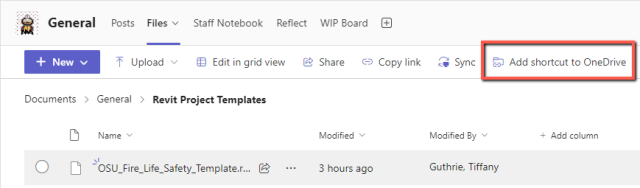
You will need to have a shortcut in OneDrive from the ENG BIM Associates Teams Files page in order to load the project template. If you haven't set this up already, in Microsoft Teams, go to the Files tab of the ENG BIM Associates Teams page and browse to Documents > General and click to open the folder called Revit Project Templates. Then click the button to Add shortcut to OneDrive. You should only have to complete this step once.
Make a new file
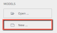
From the Revit Home screen, click the button to make a new model, or go to File > New > Project.
Browse to the Revit Project Templates folder under your OneDrive. Select the OSU_Fire_Life_Safety_Template. You must use this template! Where the dialog says Create New, be sure that Project is selected.

Optional tip: if the New Project dialog does not list the OSU templates by default, you can change that. Refer to Setting Default Path to Revit Templates before returning to this article.
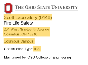
Edit the splash screen to update the building name and number, street address, and campus. Also edit the construction type shown in the archived drawings; typically the construction type would be written as a Roman numeral (I, II, III, IV or V) followed by the letter A or B. If you do not know the construction type, change the construction type to say "Unknown" until the correct type can be determined.
You will need to save the model temporarily in a local network location before loading it to the cloud. Save the file with the name as shown on the splash screen, with the format: Building Name (####) Fire Life Safety.rvt.
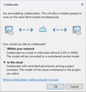
Next go to Collaborate > Collaborate. Choose the option for In the cloud and click OK.
In the Ohio State University account, browse to the applicable building and choose the Disciplines folder. Click Save. Wait a few moments for the model to load and click Close when the button appears. The model is now a workshared cloud model.
Link in the architectural model
Open the Site_True North plan view and go to Insert > Link Revit.
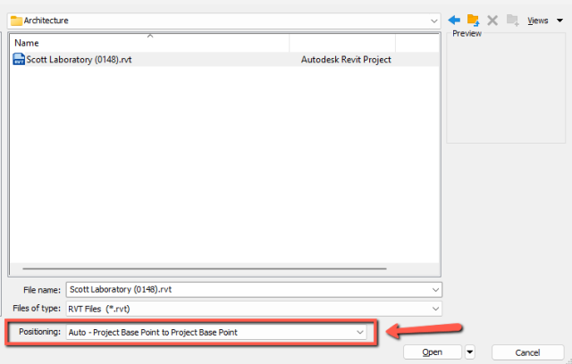
Browse to the Architecture folder and click the architectural model once to select it, but don't insert it yet. At the bottom of the dialog box, set Positioning to Auto - Project Base Point to Project Base Point. Then click Open.
Update Coordinates to Match Architectural Model (Optional)
Because the FLS plans are not intended to include any model geometry, only annotation, this step is not strictly necessary, but it is still a recommended practice.
Locate the Project Base Point (PBP) in the Site_True North view. Place your cursor on top of the PBP and hit the Tab key until it highlights the PBP from the linked architectural file. Remember, the PBP of the current file is in the same place, so be sure not to select that one. (If you have trouble, you can select the PBP from the current model and temporarily hide the element for a moment.) You will know you have selected the PBP from the linked architectural model because it will show a link symbol.
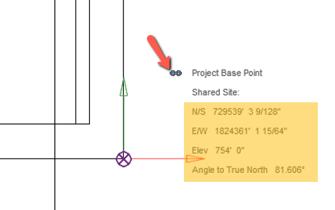
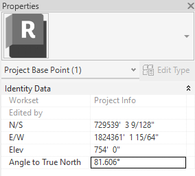
Note down the N/S and E/W coordinate data, elevation, and angle to true north. You will need to enter the same info into the active model.
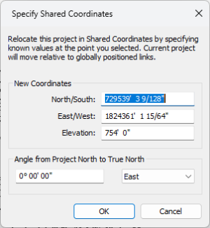
Click away or hit the Esc key to deselect the linked PBP. Go to Manage > Coordinates > Specify Coordinates at Point and select the center of the PBP. Enter the same values that were in the linked model for the coordinates and elevation. Because we can't tell from the linked information whether the angle is to the West or East, you will enter the angle in the next step after you click OK.
Select the PBP in the active model and enter the Angle to True North in the Properties box.
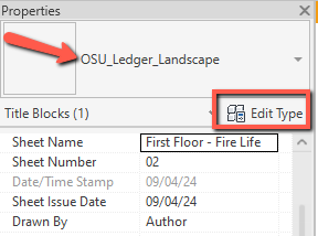
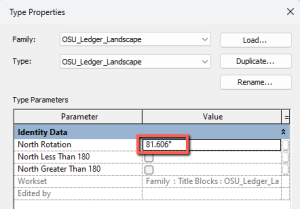
While that angle is fresh in your mind, open the floor plan sheet from the project browser. Select the title block and then click Edit Type in the Properties box. Enter the same angle in the North Rotation field and click OK to close.
Set up levels and views
Adjust levels
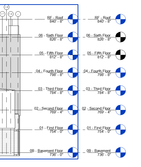
Go to an elevation view that shows the linked model as well as the levels in the active model. Edit the levels so that they match the elevations and the level names of the linked model exactly. You may need to move, add or delete some, depending on the building. Note that some of the level heads will appear black at first, but they will turn blue once the plans for those levels are created.
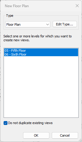
If there are any levels that do not have plan views yet, add them by going to View > Plan Views > Floor Plan. Make sure the Do not duplicate existing views box is checked and select all the plans on the list and click OK.
Place plan on title block to determine scale
Determine the plan view for the level with the largest footprint. (This is usually the first floor, but not always.) If it is the first floor, it should be on the sheet that already exists in the set. If it is not the first floor, create a sheet for it by going to View > Sheet and selecting the OSU_Ledger_Landscape title block for an 11x17 sheet. Drag the largest plan view of the largest floor from the Project Browser onto the sheet.
Change the scale of the plan view to be the largest scale that fits on the title block without extending past the boundary. If the Wall Rating Legend is not already on the sheet, be sure to add it to the sheet before determining the best scale. Note: if the scale of the Wall Rating Legend is significantly different from the scale of the plan, you will need to change the scale of the legend view to match the plan scale and realign the wall rating components and the text.
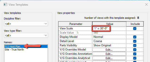
When you have determined the best scale, go to View > View Templates > Manage View Templates and select the template called FLS Host Plan. Edit the View Scale to the scale you have chosen and click OK.
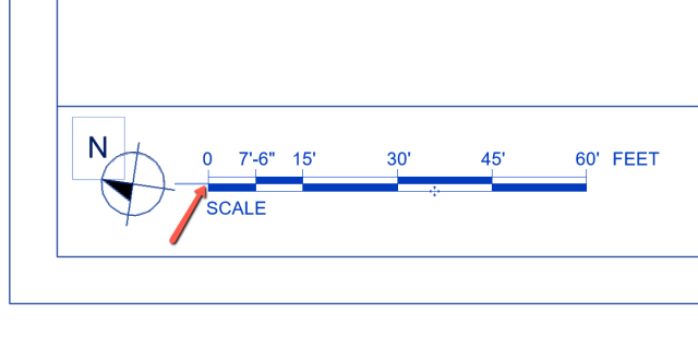
Add the appropriate graphic scale to the title block. There is an invisible line in the title block near the north arrow, and the insertion point of the scale should snap to the end of it.
Adjust Visibility/Graphics for each plan view
Make sure the FLS Host Plan view template is applied to all plan views.
Next you will need to open each plan and make a few changes in Visibility/Graphics.
- Go to the Revit Links tab in the Visibility/Graphics Overrides dialog box and check the box for Halftone.
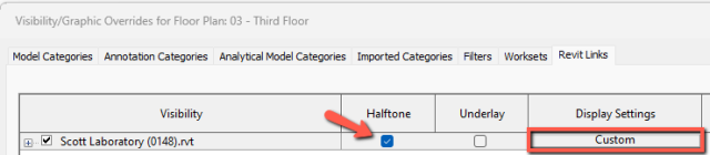
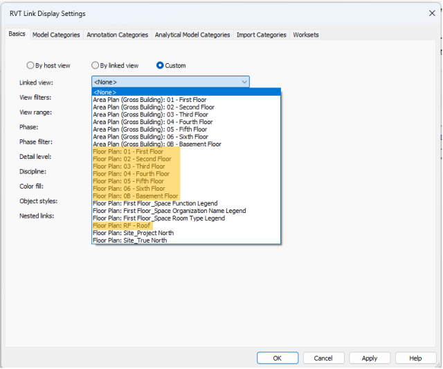
- Still in the Revit Links tab, click to open the Display Settings for the linked model. On the Basics tab, choose Custom.
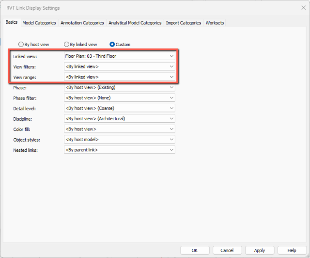
- Use the pull-down menu to set the linked view for the floor level of the plan you are working in. Choose the view with the format Floor Plan: ## - XXXX Floor, such as Floor Plan: 03 - Third Floor. Be sure not to select the Area Plans.
- Still on the Basics tab, use the pull-downs to change the View Filters and the View Range to <By linked view> and click OK to finish.
- The plan you edited should include room tags and should appear screened back in gray. Repeat this setup process for each floor.
Set up remainder of sheets and sets
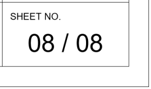
Create the remainder of the sheets needed for each plan using the same OSU_Ledger_Landscape title block as before and dragging each plan to a sheet. Once all the sheets are created, you can select the Wall Rating Legend and graphic scale from one sheet, Copy to Clipboard and Paste Aligned to Selected Views for all the other sheets. Revise the sheet numbers so that the lowest level is on sheet number 01, and each subsequent level has the following number. Note that the sheet number does not usually match the level. Also edit the total number of plans in the set for each sheet.
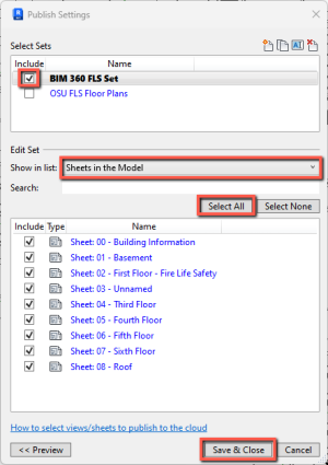
Next, add the sheets to the BIM 360 FLS Set by going to Collaborate > Publish Settings. Check the box next to BIM 360 FLS Set and pull-down the menu under Edit Set to Sheets in the Model. Choose Select All and then click Save & Close. Once published, these sheets will be visible through the BIM 360 web viewer.
Add fire ratings to plans
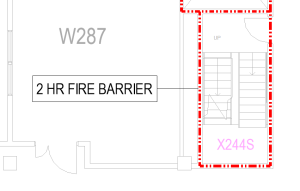
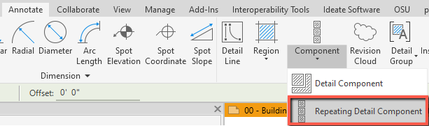
Return to the plan views and add the fire ratings shown in the archived drawings by going to Annotate > Component > Repeating Detail Component.
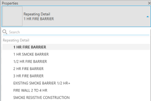
Select the type of rating you need from the Properties box.
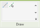
Trace the centerline of the rated walls with the default Draw Line option, or you can go to Modify > Pick Lines and select the centerline of the walls to add the repeating detail component to the length of the wall.
Add tags (optional)
If desired, you can add detail item tags by going to Tag by Category and clicking one of the rating lines. The text in the tag is populated by the name of the detail component.